
So.. this is a pipe dream I’ve had for a while, and in this post I will (attempt) to describe how it all came together into a nice little project.
I want to be able to monitor the houses’ electricity usage from the office – there are a half dozen products that can do this already, but I “think” i can do it better.
And yes, before you ask, I know I could just get a smart meter installed (and use the live usage meter) but to be honest I don’t fancy the idea of the electricity company being able to impose flexible tariffs that just so happen to charge me the most for electricity at the same time I am at home using it.. Anyway, smart meters are for another post, not this one.
The idea is this. Get a current transformer, connect it to a a Arduino Uno, use some wireless transmitters to send the current usage info to another Arduino Uno where the information will be displayed to me. Simples.
Part 1 – Current Sensing
First thing is to find a example where the Arduino can read in a current from a current transformer. openenergymonitor.org offered an attractive solution. This page provided me with a great start. https://learn.openenergymonitor.org/electricity-monitoring/ct-sensors/interface-with-arduino

I bought their recommended current meter transformer from fleaBay (a SCT-013-030) and created a PCB in EasyEDA from their reference design.


A week later the PCBs arrived from JLCPCB and i built them up, ready for testing.
Using the libraries and examples provided I was able to knock up a sketch that output measured current on serial debug. Code is attached below.
// EmonLibrary examples openenergymonitor.org, Licence GNU GPL V3
include "EmonLib.h"                   // Include Emon Library
EnergyMonitor emon1;                   // Create an instance

void setup()
{
Serial.begin(9600);
emon1.current(A1, 60.14);             // Current: input pin, calibration.
}

void loop()

{
double Irms = emon1.calcIrms(1480);  // Calculate Irms only
double power = (Irms*245.0);
Serial.println(power);           // Apparent powe
Serial.print(" ");
Serial.println(Irms);               // Irms
Serial.print(" ");
}
I had to faf around with the second variable in the emon1.current() function to get the measured current calibrated. This was mostly-trivial as I used a external electricity meter that measured current, a oil radiator to produce a fixed current and finessed it to get a accurate value.
This being a current transformer it’s never going to be fantastically accurate, mainly for the reason that to truly calculate Power, you need to know Current and Voltage (and their phase shift), and the current transformer can only measure current with no regard to phase shift or voltage. In the technical sense, I’m only really measuring kVA but let’s pretend it’s kW as it looks cooler on the meter in the end.
But, for a simple power meter, this is good enough. We can guess that the voltage will be around 230~240V (see later) and we can dream of a power factor of 1 (most of the large loads in the house are purely resistive).
In the end, I achieved about 0.1 amp accuracy and I am happy with this. Onto the next part……
Part 2 – Radio Link
I need some way of transmitting this info from one Arduino to another. While at university a lecturer of mine had some success with using NRF24L01 modules to create a wireless thermostat. These modules seemed perfect so I bought two from fleaBay.

So the radio modules arrived, and I looked for some sort of tutorial for how to get these working. I found what I wanted at HowToMechatronics.com, their tutorial on the NRF24L01 was fantastic. Here is the URL. https://howtomechatronics.com/tutorials/arduino/arduino-wireless-communication-nrf24l01-tutorial/

I set up two Arduino Unos, connected them to each radio module using the pinouts suggested (see above), downloaded the NRF24 libraries, and loaded the TX and RX sketches into the Unos.

And.. the examples worked perfectly. Luck was on my side. I was transmitting “Hello World” from one Uno to another, and seeing it being printed out over serial. The example code(s) are below.
/*
* Arduino Wireless Communication Tutorial
*     Example 1 - Transmitter Code
*
* by Dejan Nedelkovski, www.HowToMechatronics.com
*
* Library: TMRh20/RF24, https://github.com/tmrh20/RF24/
*/
#include <SPI.h>
#include <nRF24L01.h>
#include <RF24.h>
RF24 radio(7, 8); // CE, CSN
const byte address[6] = "00001";
void setup() {
  radio.begin();
  radio.openWritingPipe(address);
  radio.setPALevel(RF24_PA_MIN);
  radio.stopListening();
}
void loop() {
  const char text[] = "Hello World";
  radio.write(&text, sizeof(text));
  delay(1000);
}
/*
* Arduino Wireless Communication Tutorial
* Example 1 - Receiver Code
*
* by Dejan Nedelkovski, www.HowToMechatronics.com
*
* Library: TMRh20/RF24, https://github.com/tmrh20/RF24/
*/
#include <SPI.h>
#include <nRF24L01.h>
#include <RF24.h>
RF24 radio(7, 8); // CE, CSN
const byte address[6] = "00001";
void setup() {
Serial.begin(9600);
radio.begin();
radio.openReadingPipe(0, address);
radio.setPALevel(RF24_PA_MIN);
radio.startListening();
}
void loop() {
if (radio.available()) {
char text[32] = "";
radio.read(&text, sizeof(text));
Serial.println(text);
}
}I modified the code (You’ll see the rest of it shortly) to dump the example char and implemented a double instead. I set the double to some made up number in the Tx sketch, updated the Rx sketch, uploaded and I could see the number being transmitted instead of the Hello World example. Success!

I have made up another shield PCB to connect the NRF24L01 modules to the Arduino UNO, but I have not set them off for manufacture yet.
Part Three – Wireless Power Measurements
Now I had to merge the two parts together into one. This was surprisingly easy. I should say here that I am a awful coder, I am far happier in the world of Hardware but for this project I had to break out my rarely used C skills.
I left the Rx code for the moment and concentrated on the Tx code. I took the EmonLibrary and spliced it into the Tx code from HowToMechatronics and added my own touches for a combination of sarcastic comments and hopeful serial debug messages to help me debug this mess.
I also too the time now to swap out the power function for the higher power option – there is a large amount of concrete and bricks between the end Tx and Rx locations. Code is below.
/*  Wireless Power Monitor
 *
 *  Transmit Code
 *
 *  Some code from Dejan Nedelkovski, www.HowToMechatronics.com
 *  Other code from openenergymonitor.org who deal with Emon stuff.
 *
 *
 */

#include "EmonLib.h"                     // Include Emon Library for dealing with the current clamp
EnergyMonitor emon1;                     // Create an instance

#include <SPI.h>                         // Include SPI lib
#include <nRF24L01.h>                    // Include radio lib
#include <RF24.h>                        // Include radio lib
RF24 radio(7, 8); // CE, CSN             // set up pins
const byte address[6] = "00005";         // set up "radio pipe"

void setup() {
  Serial.begin(9600);
  emon1.current(A1, 60.14);             // Current: input pin, calibration.
  radio.begin();                        // begin radio stuff
  radio.openWritingPipe(address);       // open up "radio pipe"
  //radio.setPALevel(RF24_PA_MIN);      // uncomment for low power mode
  radio.setPALevel(RF24_PA_MAX);        // uncomment for high power mode
  radio.stopListening();                //Set module as transmitter

  Serial.println("Tx startup...");      // debug so we can see we're leaving setup now

}
void loop() {
  double Irms = emon1.calcIrms(1480);  // Calculate Irms only

  double holding = Irms;                // shove the irms value into "holding"

  //radio.write(&text, sizeof(text));
  radio.write(&holding, sizeof(holding));     // take "holding" and transmit it
  Serial.println("radio payload sent, probably");
  delay(500);

}
I hope the comments more or less explain what is going on. Basically, we’re recording the current using emon1.calcIrms() function, then using the radio.write() function to send it across the radio link. Also for some debug, we then take the ‘holding’ double and send it down the serial line, so we can further calibrate the current measurement if we need. we then have a 500ms delay in there for some stability.
The nice thing about this project is I can tinker live with the Tx code and get it working the way I want while the Rx Uno just spits out on serial debug whatever is coming over the radio link.


Once I was happy with the state of the Tx code (as it appears above) I took my hardware and hooked it up the house electricity meter – the meter has 4 thick 25 or 16mm2 double insulated cables.
The current meter just goes around any one of the 4 main cable that go to the meter. I choose the easiest one to reach as to not disturb the wires too much. You must exercise caution while doing this.
Also make sure to plug the current transformer in the Arduino first before installing the current transformer as to avoid undesirable voltages on the output of the transformer (before the burden resistor is connected). I then leave the Uno on the floor nearly to transmit the current measurement to the other Arduino. At some point I’ll have to make a nice project box enclosure for all this.
Back to the Rx Arduino Uno. I am back in the office and I can see that the current double is coming through clearly. Thankfully, it seems the radios have enough power to go the distance (which is about 20~30 meters free air not including probably 6 foot of concrete, brick, and soil)
I modify the code a bit to take the current measurement and multiply it with 235 to get a value for Power (in kW, or actually kVA, see above).
This is not the most accurate (for many reasons, but mainly) as we’re taking a guess at the voltage, in the UK in theory it could range from 216V to 253V, it is supposed to be 230V but in many places it is actually 240V.
A little history – the single phase domestic voltage in the UK was set at 240V at some point in the 20th century, and since changed to 230V in January 2003 to harmonise with Europe. However, in reality nothing changed – the standard is now 230V -6% +10% (i.e. 216.2 V – 253.0 V) as lots of transformers that output 240V are still in service. Rather amusingly, the voltage I measure at the plug in the office is 250V!
Now we have power used being sent out over debug, and for my own interest I am also saving the serial debug in the hope of some pretty Excel graphs in the future.
Part 4 – A Fancy Meter
I was going to finish this project by using a boring 2 line LCD display and just displaying the power usage on there, but while I was endlessly scrolling on the internet I found the above post on reddit.
In the link above, a redditor uses analogue voltmeters for a clock – the key point being that this shows how a Arduino can drive a analogue voltmeter with some modification. This is by no means a new idea, people have been controlling meters like this since at least May 2008 (looking on YouTube).
The meter range can be controlled by using a PWM output controlled by the analogue.Write() function on a PWM pin. The analogue meter will need to be opened and modified by removing the diode, resistor and capacitor, and replacing it with a suitable resistor, so that 5v gives a full scale reading. This involves some trial and error. I found that for my meter, I needed a 4k7 resistor.
This page here goes into better detail with how to modify a meter for this type of use https://michaelteeuw.nl/post/174972004187/what-time-is-it-fathers-day.
I then had to think for a bit about how i was going to scale the “power” value so it could be used in the analogue.Write() function. I came up with this.
    double metera = (power/10000);           // not very elegant.
    double meterb = metera * 255;
    if (meterb > 255) {
      meterb = 255;
    }
    analogWrite(5, meterb);
I decided that the maximum value on want on my meter will be 10,000 or 10kW. I take the ‘power’ value and divide it by the max value to get a value from 0-1, which I then multiply by 255 as 255 is the maximum analogWrite value. The if statement makes sure that if the power goes above 10kW (which happens occasionally) then the value sent to analogWrite is no higher than 255. I incorporated this into my Rx code, and this is the result.
/*  Wireless Power Monitor
 *
 *  Recieve Code
 *
 *  Some code from Dejan Nedelkovski, www.HowToMechatronics.com
 *
 *  Code has been modified to spit out Current on serial only (for computer logging)
 */

#include <SPI.h>                         // Include SPI lib
#include <nRF24L01.h>                    // Include radio lib
#include <RF24.h>                        // Include radio lib
RF24 radio(7, 8); // CE, CSN            // set up pins
const byte address[6] = "00005";        // set up "radio pipe" (this case, address 5)


void setup() {
  Serial.begin(9600);
  pinMode(5, OUTPUT);
  radio.begin();
  radio.openReadingPipe(0, address);
  //radio.setPALevel(RF24_PA_MIN);      // uncomment for low power mode
  radio.setPALevel(RF24_PA_MAX);        // uncomment for high power mode
  radio.startListening();               //Set module as Rx
  //Serial.println("Rx startup...............");

  analogWrite(5, 0);                    // This mass of analogueWrite() is just a fancy needle movement.
  delay(500);
  analogWrite(5, 50);
  delay(500);
  analogWrite(5, 100);
  delay(500);
  analogWrite(5, 150);
  delay(500);
  analogWrite(5, 200);
  delay(500);
  analogWrite(5, 255);
  delay(500);
  analogWrite(5, 0);
  delay(500);

}
void loop() {


  if (radio.available()) {                        // if there is radio crap avaliable....
    double holding = 0.66;                      // set up "holding" and give it 0.66 as a temp value
    //char text[32] = "";
    radio.read(&holding, sizeof(holding));       // shove whatever came out of radio into "holding"
    //Serial.print ("Current = ");
    //Serial.println(holding);
    double power = (235 * holding);              // "holding" should be a current, so * 235 to get Watts
    //Serial.print ("Power = ");
    Serial.println(power);                      // spit out "power" on debug for logging if wanted
    //Serial.println("");

    // while we're here.....                     // this code takes the "power" value, and produces a 0-255
    double metera = (power/10000);               // scaled value that can then be piped into AnalogueWrite
    double meterb = metera * 255;                // where it is then interpreted by the analogue meter
    if (meterb > 255) {                           // if power is ever higher than 10kw then the analoguewrite
      meterb = 255;                               // will go higher than 255. this if corrects if it happens.
    }
    analogWrite(5, meterb);
    //Serial.println(meterb);


  }

}
We upload this to our Rx Arduino, and confirm that power is still coming out over debug. I then connect the modified analogue meter to pin 5 and the the meter jumps to the correct position on the scale! Great to see that it’s working. now for a custom range.


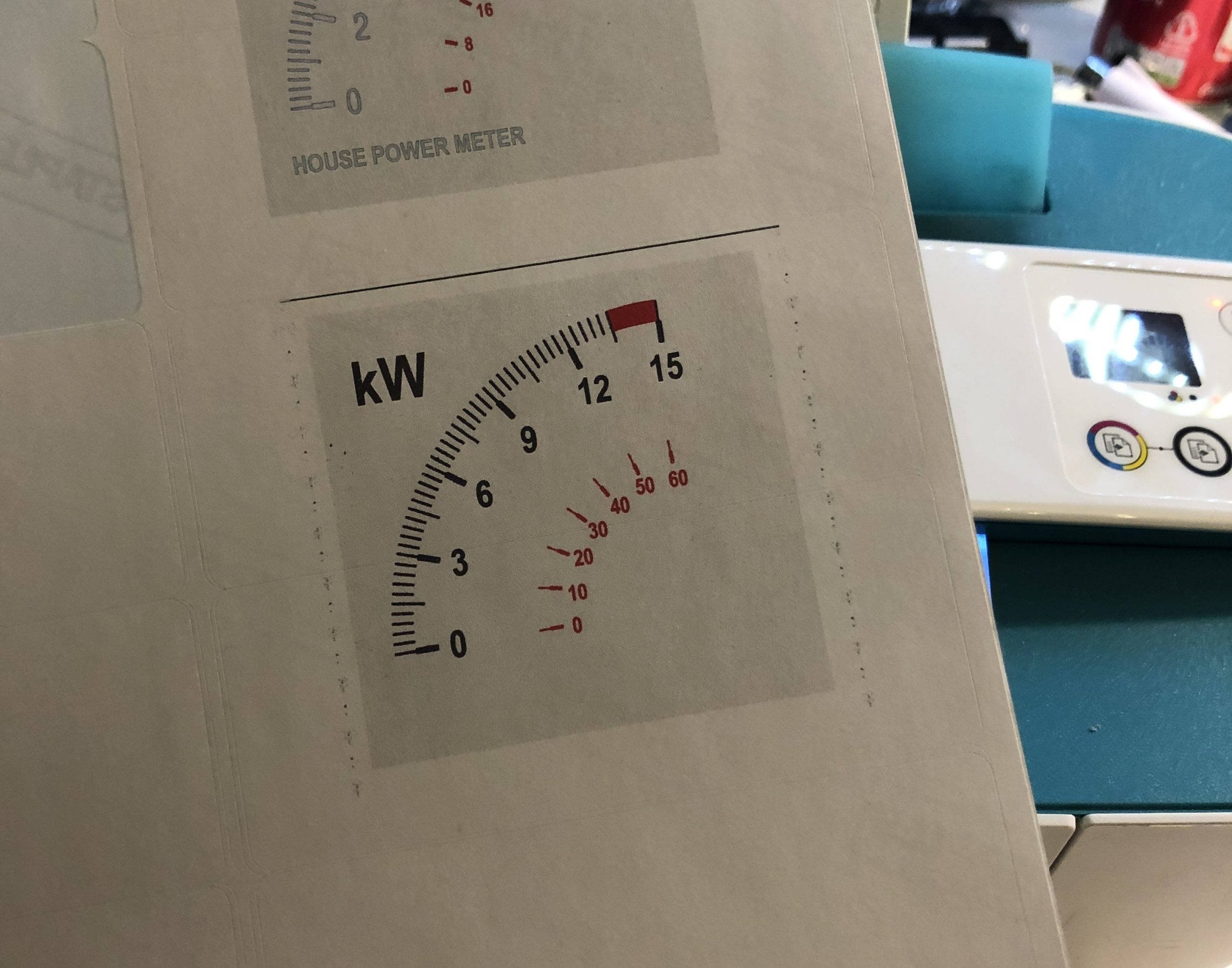
The meter previously was a 0-250VAC meter – I modified it slightly as mentioned above. I popped out the metal front panel, scanned it using a flatbed scanner, and then used GIMP to create myself a new front panel, which printed out on some stickers, then applied to the metal front panel. For some added drama I marked the top end of the meter range in red – if we ever get up that high we’d be at risk of blowing the mains service fuse. I really should buy some sheets of larger stickers but it’s still a result!

So.. this is where I leave you. It works, I have achieved my goal. The code needs optimisation, the Unos need some more custom radio shields, and I need some sleep. but, I hope it brings you some joy reading this post. Let me now what you think, if you want.


Recent Comments